Hardware Assembly Instructions
This tutorial provides step-by-step instructions for assembling the KLASK Hardware components. Follow these steps carefully to ensure proper assembly and functionality.
Overview
The KLASK robotic system consists of three main assembly groups, the board frame fixing the playing field, the gantry system providing the motion mechanism for each player side, and the camera mount mounting the camera and the lights above the board.
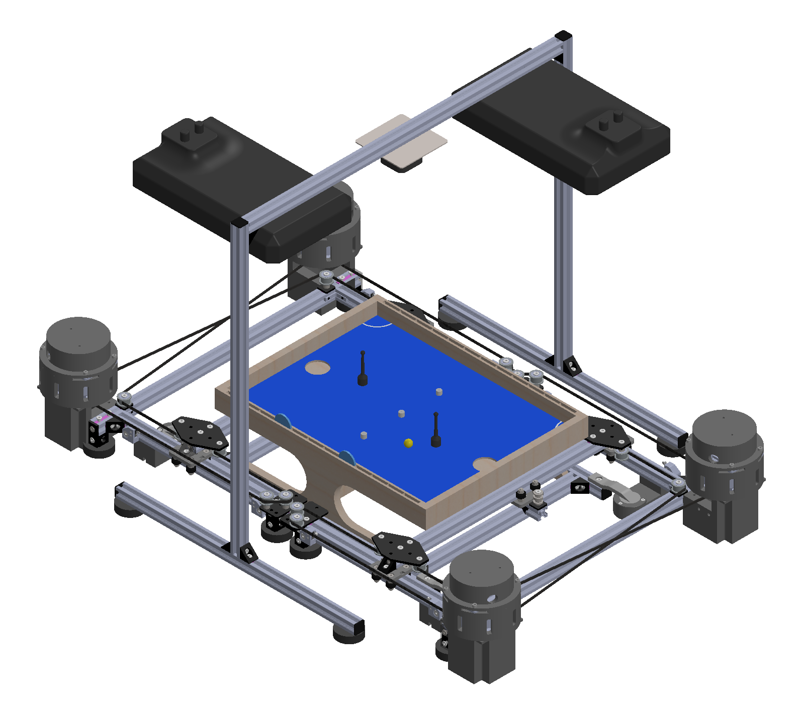
The following sections provide detailed assembly instructions for each of these groups. The CAD models shown here and the files for 3D printing can be found in this repo under hardware/cad/. A complete Bill of Materials (BOM) for all parts needed for the assembly is provided at the end of this tutorial.
Board Frame
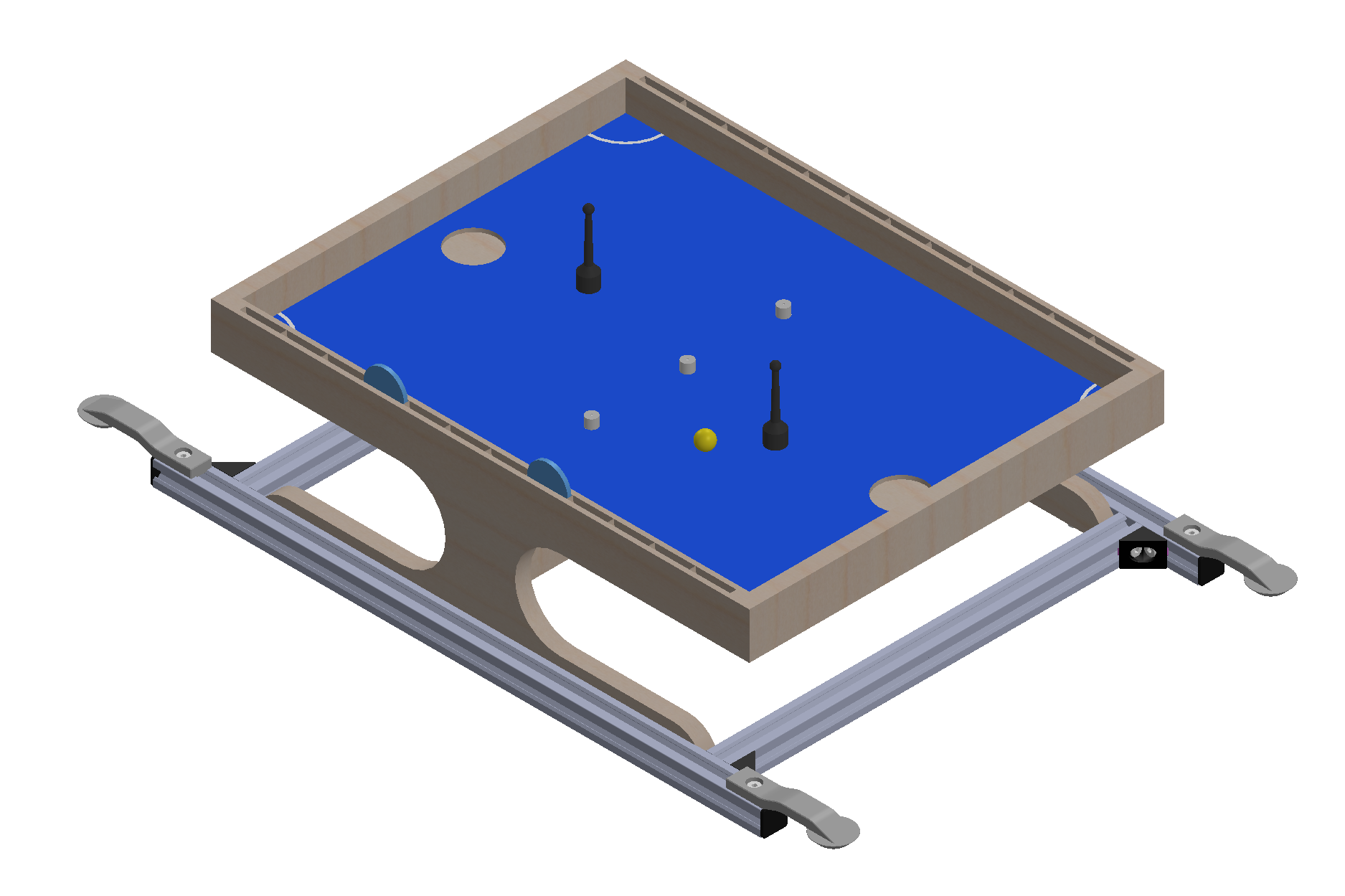
Bill of Materials (BOM) for the Board Frame
The board frame consists of the following parts:
| Pos. | Name | Description | Quantity | Link |
|---|---|---|---|---|
| 1 | V-Slot 20x20 Linear Rail | L = 500 | 2 | Link |
| 2 | V-Slot 20x20 Linear Rail | L = 340 | 2 | Link |
| 3 | Frame Centering Bridge | 3D-Print | 4 | |
| 4 | Black Angle Corner Connector | 4 | Link | |
| 5 | End Cap | 4 | Link | |
| 6 | Low Profile Screw | M5x8 | 12 | Link |
| 7 | Tee Nut | M5 | 12 | Link |
Assembly Instructions for the Board Frame
The assembly of the board frame is straightforward. Start by cutting the V-slot beams to the specified lengths if not already done and print the frame centering bridges. Once all parts are ready you can simply assemble them as shown in the image below. Make sure that the KLASK board fits tightly into the frame. The exact Pos.ing of the frame centering bridges can be adjusted later.
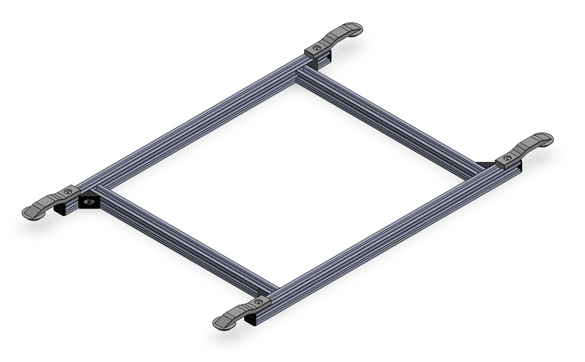
Thats all for the board frame assembly! Wuhoo! You've built the first part of your KLASK robot.
Camera Mount
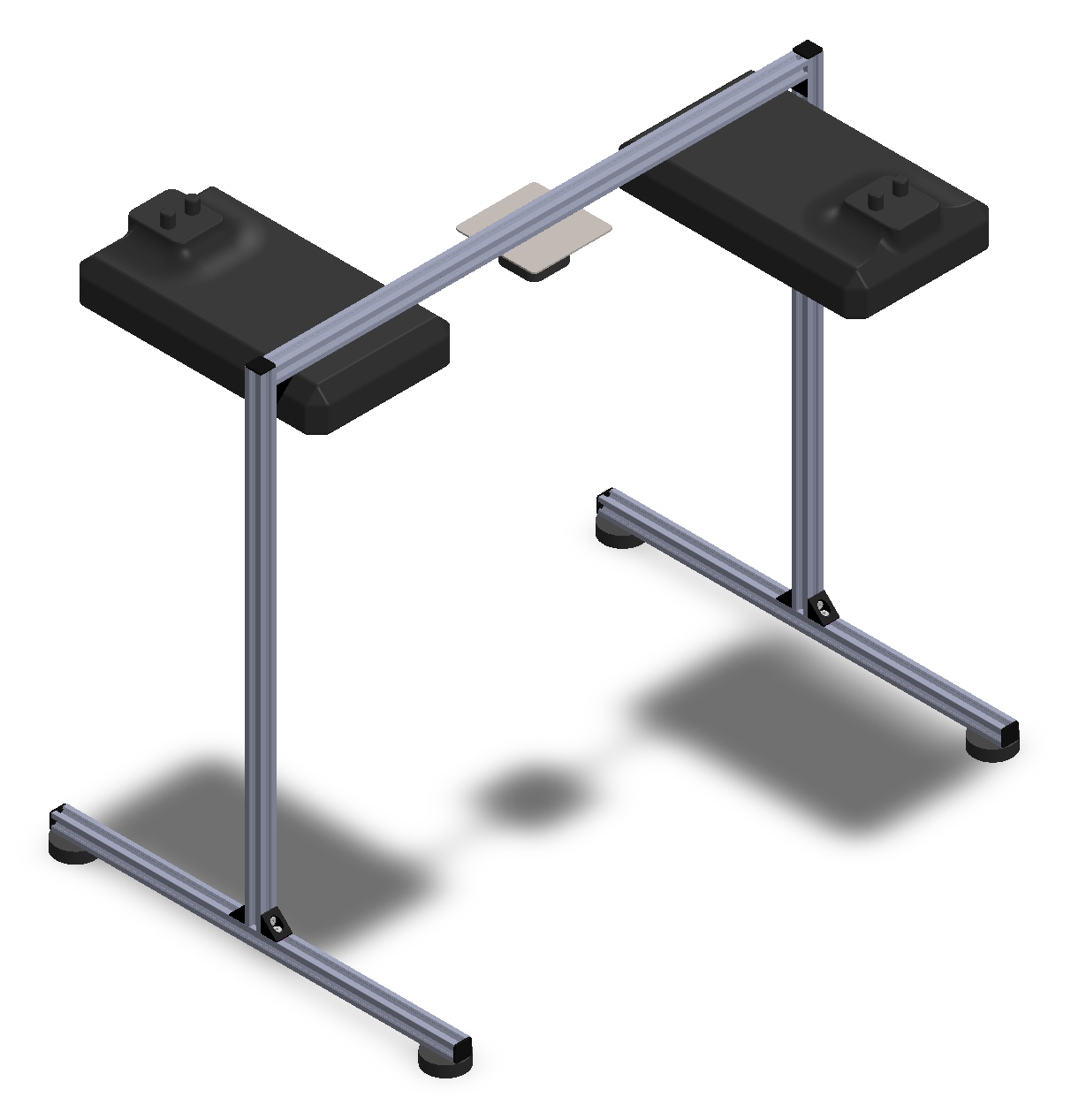
BOM for the Camera Mount
The camera mount consists of the following parts:
| Pos. | Name | Description | Quantity | Link |
|---|---|---|---|---|
| 1 | V-Slot 20x20 Linear Rail | L = 660 | 1 | Link |
| 2 | V-Slot 20x20 Linear Rail | L = 600 | 2 | Link |
| 3 | V-Slot 20x20 Linear Rail | L = 500 | 2 | Link |
| 4 | Black Angle Corner Connector | 6 | Link | |
| 5 | End Cap | 6 | Link | |
| 6 | Low Profile Screw | M5x8 | 16 | Link |
| 7 | Tee Nut | M5 | 16 | Link |
| 8 | Rubber Foot | 4 | Link | |
| 9 | Camera | 1 | ||
| 10 | Camera Mounting Plate | 3D-Print | 1 | |
| 11 | Nanlite Compac 24B | 2 |
Assembly Instructions for the Camera Mount
As with the board frame the camera mount assembly is quite simple. Start by cutting the V-slot beams to the specified lengths if not already done and then assemble the parts as shown in the image above.
To achieve the most robust scene lightning we recommend to set the DIMand CCT turning knobs on the Nanlite Compac 24B lights to maximum +.
Gantry System
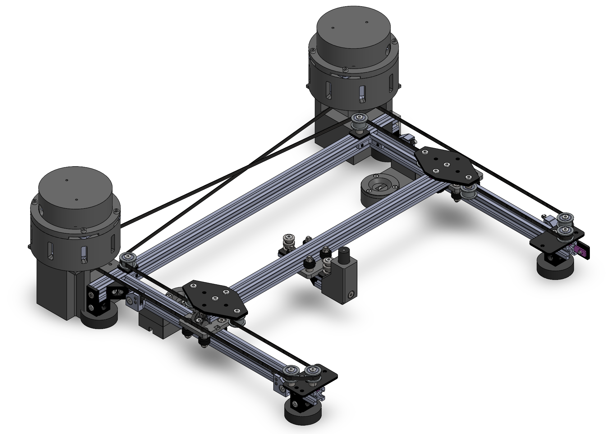
Now the most complex part of the assembly, the gantry system. This part provides the motion mechanism for the KLASK robot.
The parts needed to build one gantry system are listed below. We divide the BOM and the instructions into different sections for each sub-assembly.
Controller
First we start with the controller assembly that mounts the magnet to play the game.
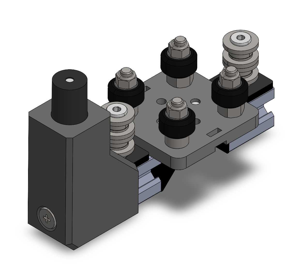
The parts needed for that are listed below.
| Pos. | Name | Description | Quantity | Link |
|---|---|---|---|---|
| 1 | Mini V Gantry Kit | 1 | Link | |
| 2 | V-Slot 20x20 Linear Rail | L = 26.5 | 1 | Link |
| 3 | V-Slot 20x20 Linear Rail | L = 31.5 | 1 | Link |
| 4 | Black Angle Corner Connector | 2 | Link | |
| 5 | End Cap | 2 | Link | |
| 6 | Low Profile Screw | M5x8 | 2 | Link |
| 7 | Low Profile Screw | M5x30 | 2 | Link |
| 8 | Self Tapping Screw | 3 | Link | |
| 9 | Tee Nut | M5 | 2 | Link |
| 10 | Slot Washer - 15x5x2mm | 8 | Link | |
| 11 | Precision Shim - 10x5x1mm | 8 | Link | |
| 12 | Aluminum Spacers | 3mm | 6 | Link |
| 13 | Peg Holder | 3D-Print | 1 |
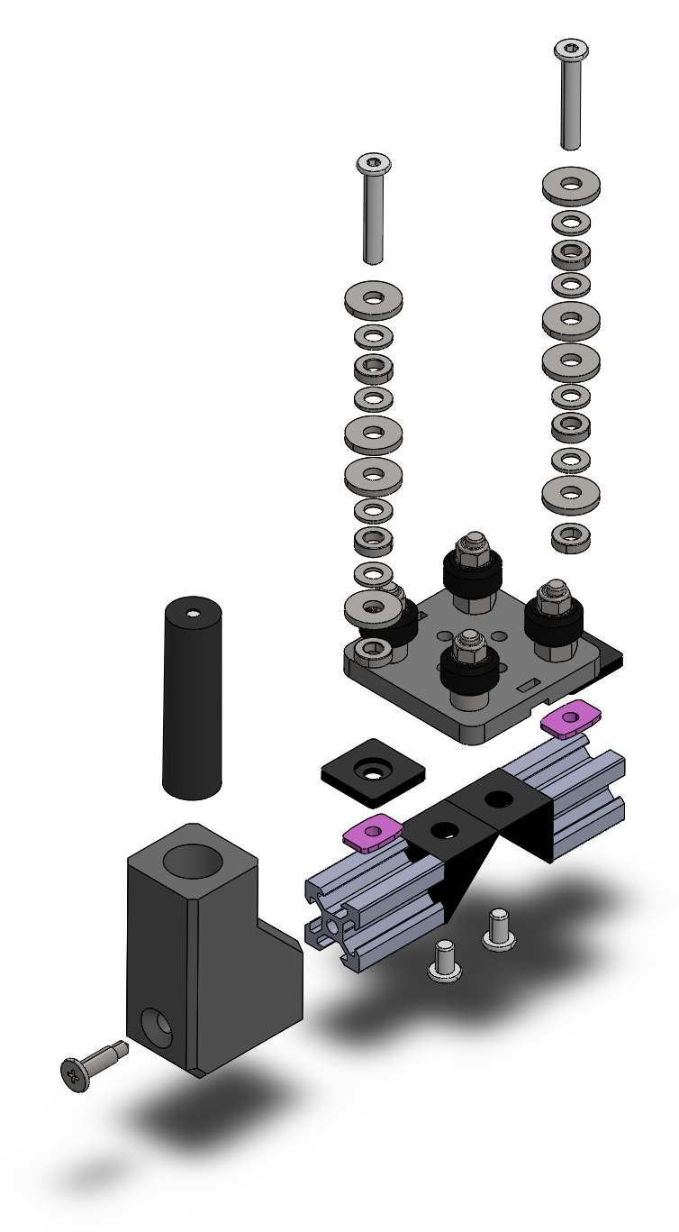
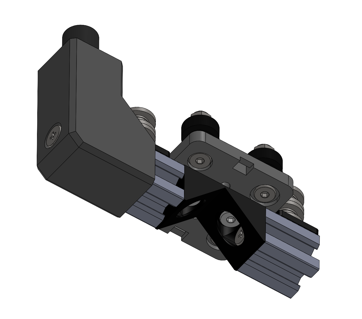
The explosion view below shows how the controller is assembled. The Mini V Gantry Kit comes pre-assembled and the longer of the two V-Slot beams is used on the side where the magnet is mounted.
Bridge
The bridge assembly carries the controller that moves along the Y axis.
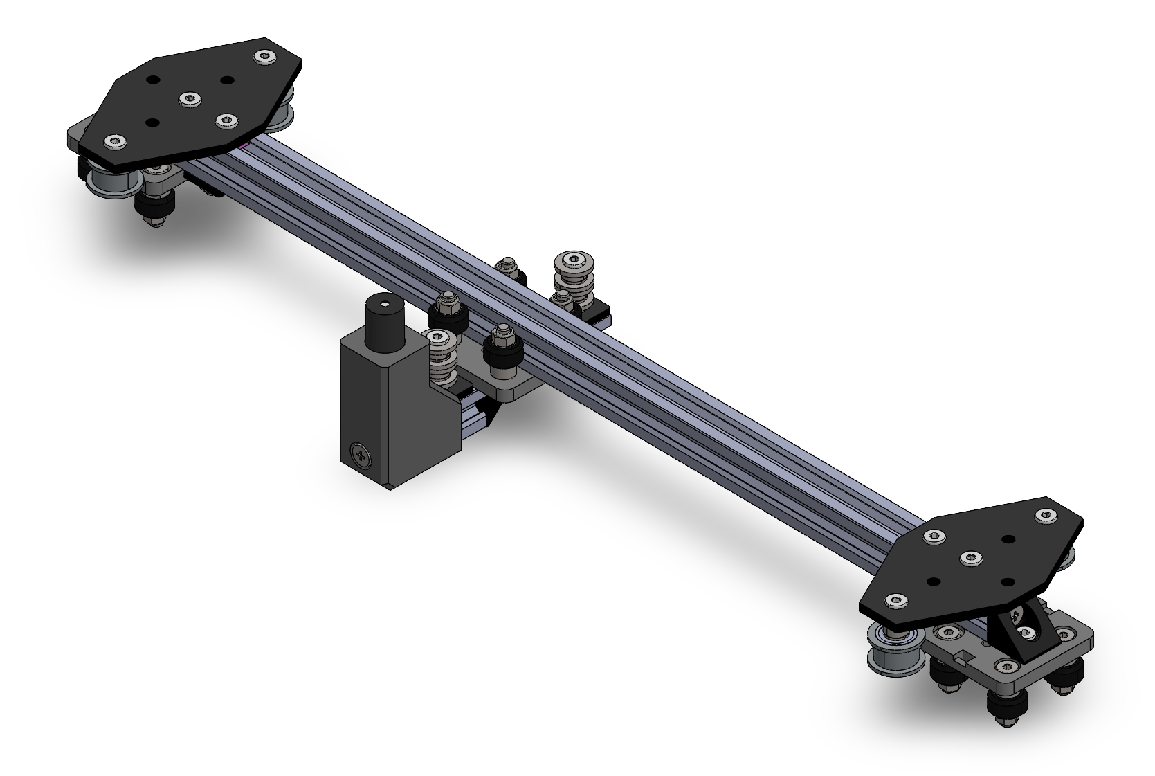
The parts needed for the bridge assembly are listed below.
| Pos. | Name | Description | Quantity | Link |
|---|---|---|---|---|
| 1 | V-Slot 20x20 Linear Rail | L = 462.7 | 1 | Link |
| 2 | Mini V Gantry Kit | 2 | Link | |
| 3 | Black Angle Corner Connector | 2 | Link | |
| 4 | Cross Joining Plate | 2 | Link | |
| 5 | Smooth Idler Pulley Kit | 4 | Link | |
| 6 | Low Profile Screw | M5x8 | 8 | Link |
| 7 | Low Profile Screw | M5x25 | 2 | Link |
| 8 | Low Profile Screw | M5x30 | 2 | Link |
| 9 | Tee Nut | M5 | 2 | Link |
| 10 | Double Tee Nut | M5 | 2 | Link |
| 11 | Self Tapping Screw | 2 | Link | |
| 12 | End Cap | 2 | Link |
The following explosion view shows how the bridge is assembled.
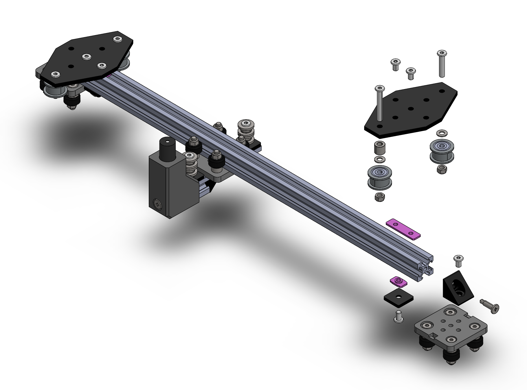
First assemble one side, then slide the controller onto the bridge beam, and finally assemble the other side.
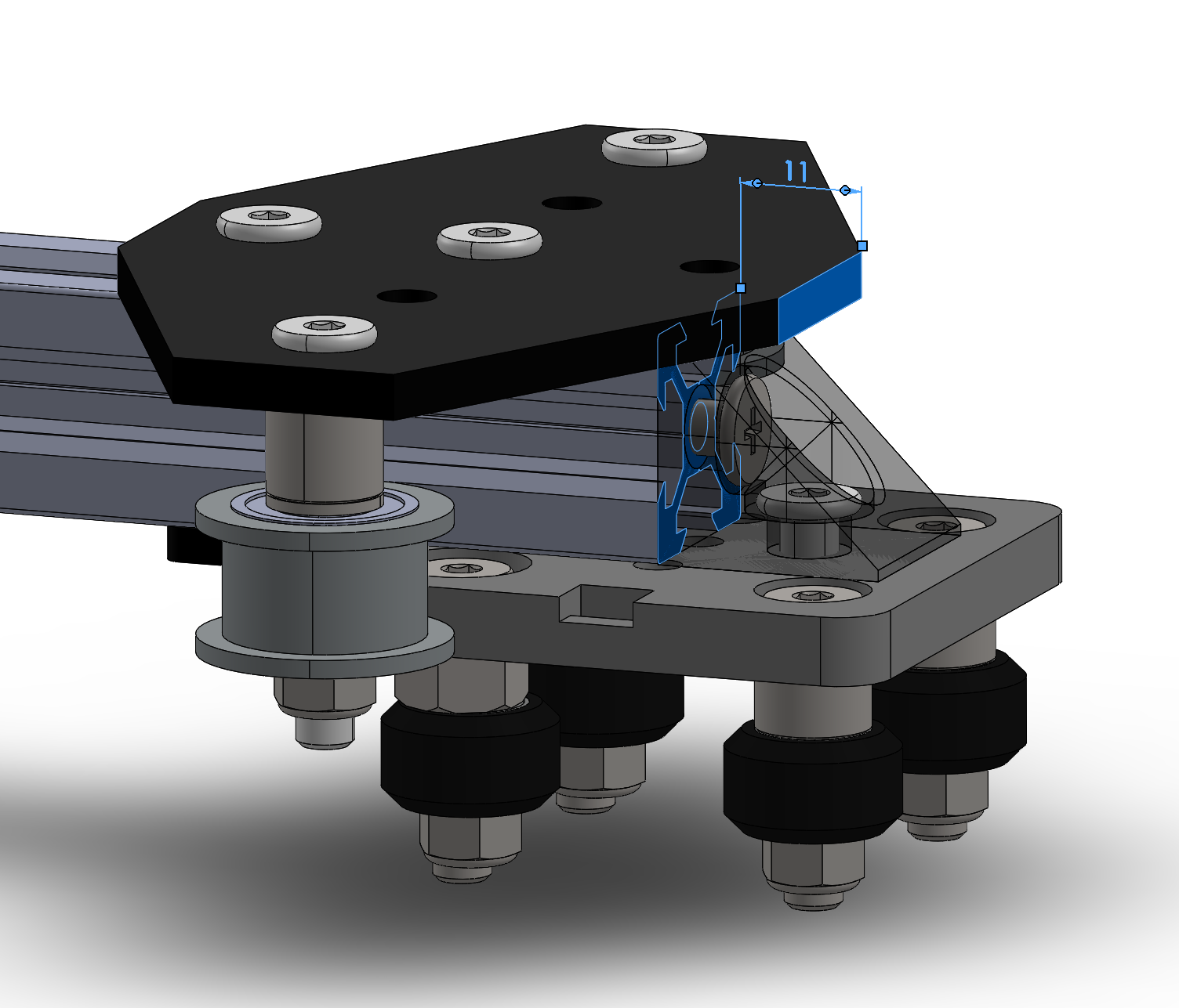
To later have an aligned idler wheel with the motor wheel, mount the cross plate with a distance of 11 mm from the end of the bridge beam as shown in the image below.
Board Frame Support
The board frame support connects the gantry system to the board frame.
It consists of the following parts:
| Pos. | Name | Description | Quantity | Link |
|---|---|---|---|---|
| 1 | Ground Plate | 3D-Print | 4 | |
| 2 | Center Plate | 3D-Print | 4 | |
| 3 | Mounting Bracket | 3D-Print | 4 | |
| 4 | Limit Switch | Würth WS-MITV THT (463093370402) | 4 | Link |
| 5 | Socket Head Screw | M2x12 | 8 | |
| 6 | Socket Head Screw | M5x30 | 8 | |
| 7 | Countersunk Screw | M3x14 | 12 | |
| 8 | Hex Nut | M2 | 8 | |
| 9 | Hex Nut | M3 | 12 | |
| 10 | Tee Nut | M5 | 8 | Link |
It is rather simple to assemble as you can see from the explosion view below.
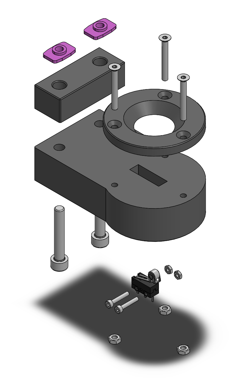
The hight of the limit switch has to be adjusted such that the actuator on the switch is pressed when the centering bridge of the board frame (which is the counter part of the cone shape) rests in it.
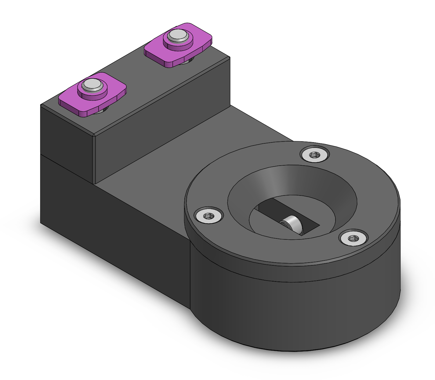
Limit Switch Mount
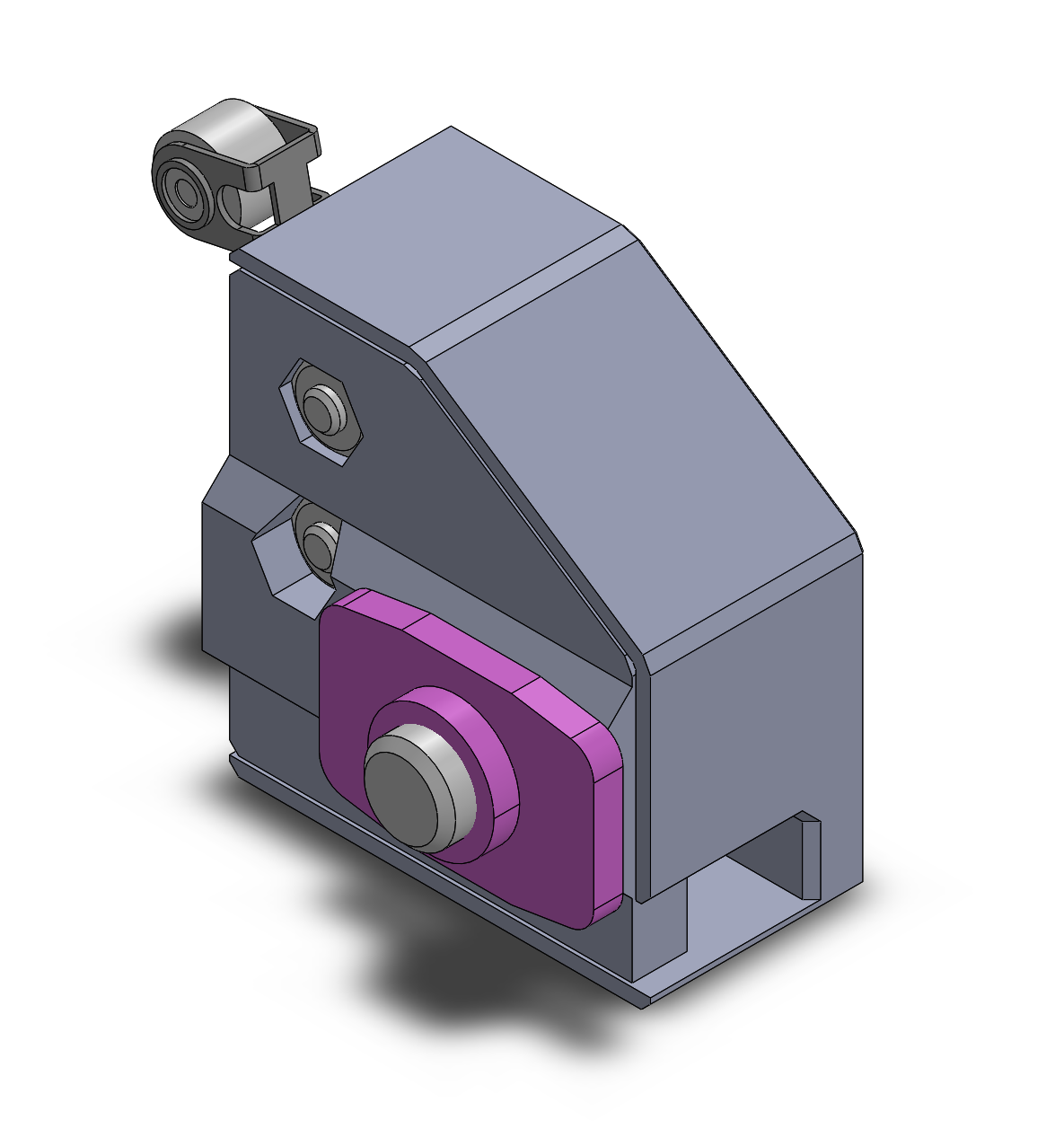
The limit switch mount holds the limit switches for the axis end stops.
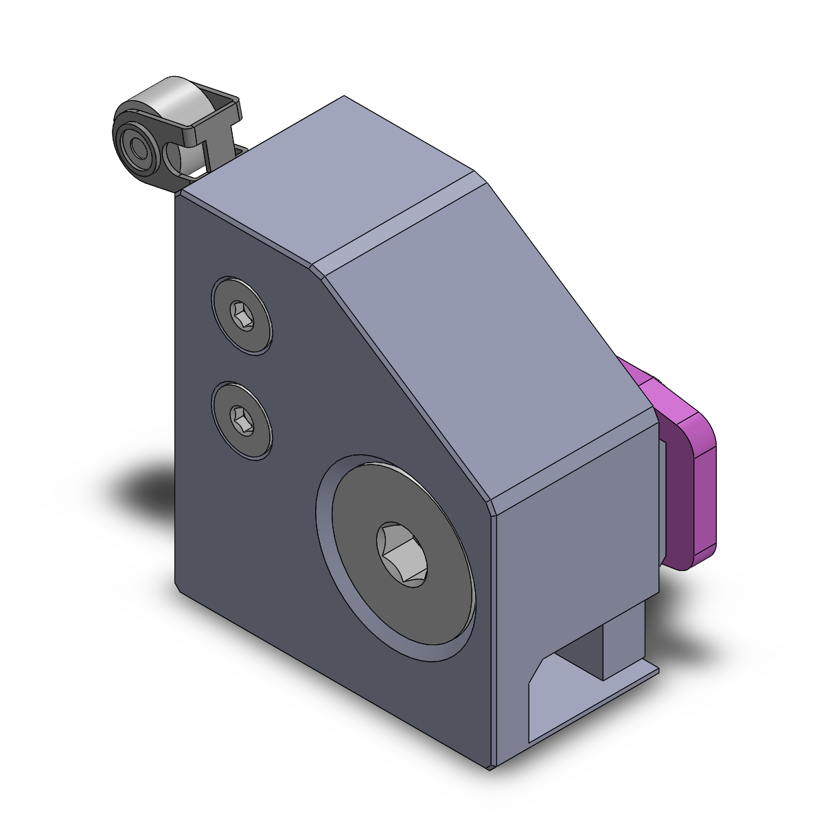
You need two of them a normal and a mirrored one. The parts needed are listed below.
| Pos. | Name | Description | Quantity | Link |
|---|---|---|---|---|
| 1 | Mount | 3D-Print | 1 | |
| 2 | Mount mirrored | 3D-Print | 1 | |
| 3 | Cover | 3D-Print | 1 | |
| 4 | Cover mirrored | 3D-Print | 1 | |
| 5 | Limit Switch | Würth WS-MITV THT (463093370402) | 2 | Link |
| 6 | Countersunk Screw | M2x12 | 4 | |
| 7 | Countersunk Screw | M5x18 | 2 | |
| 8 | Hex Nut | M2 | 4 | |
| 9 | Tee Nut | M5 | 2 | Link |
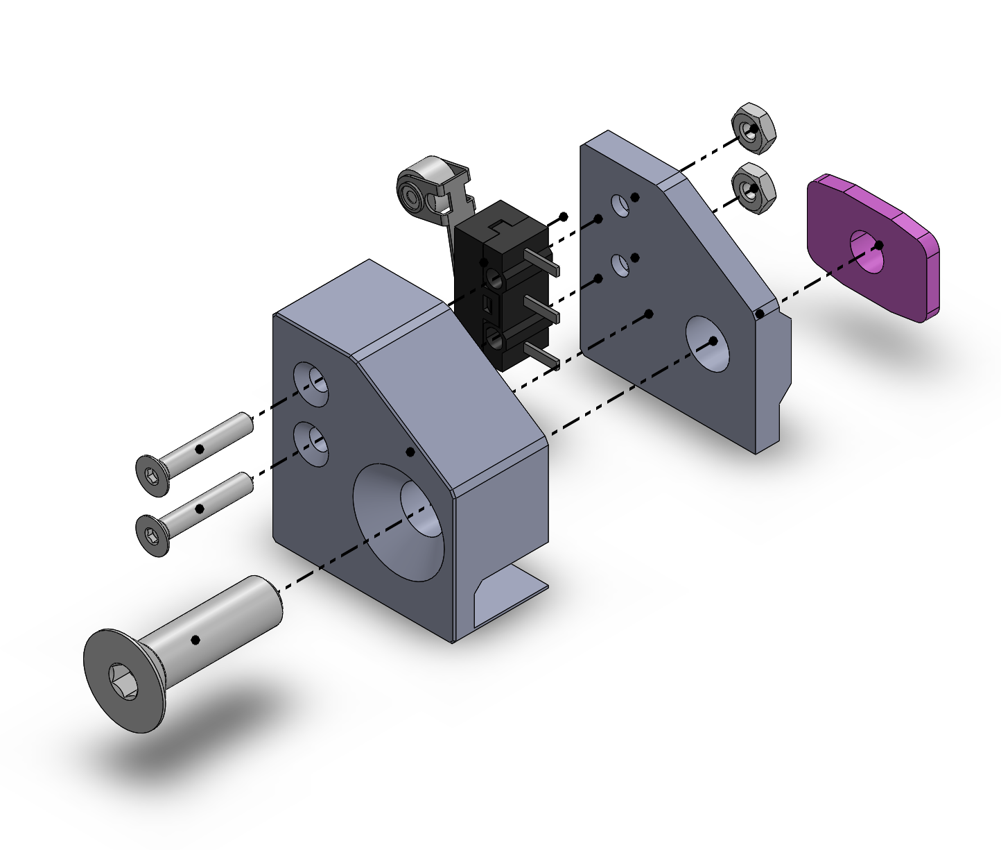
The following explosion view shows how to assemble the casing.
Gantry Frame
And now the part that holds everything together, the gantry frame.
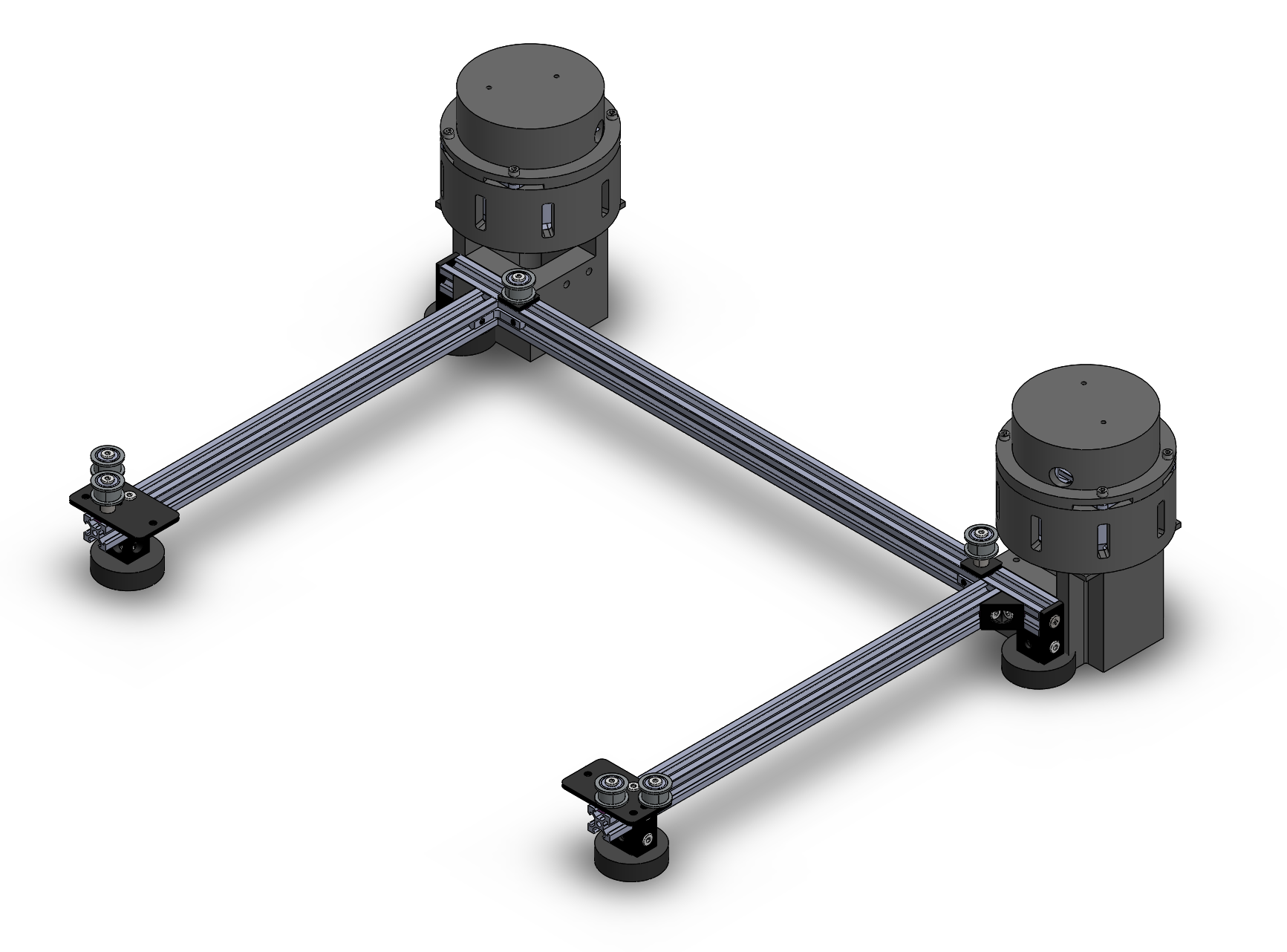
The parts needed for the gantry frame are listed below.
| Pos. | Name | Description | Quantity | Link |
|---|---|---|---|---|
| 1 | V-Slot 20x20 Linear Rail | L = 550 | 1 | Link |
| 2 | V-Slot 20x20 Linear Rail | L = 360 | 2 | Link |
| 3 | Inside Hidden Corner Bracket | 2 | Link | |
| 4 | Double Tee Nut | M5 | 5 | Link |
| 5 | Low Profile Screw | M5x8 | 18 | Link |
| 6 | GT2-2M Timing Pulley - 20 Tooth | 2 | Link | |
| 7 | Idler Pulley Plate | 2 | Link | |
| 8 | Smooth Idler Pulley Kit | 6 | Link | |
| 9 | Tee Nut | M5 | 8 | Link |
| 10 | Black Angle Corner Connector | 2 | Link | |
| 11 | End Cap | 4 | Link | |
| 12 | Precision Shim - 10x5x1mm | 6 | Link | |
| 13 | Aluminum Spacers | 9mm | 3 | Link |
| 14 | GT2-2M Timing Belt | 4 m = 13 ft | 1 | Link |
| 15 | Nylon Insert Hex Locknut | M5 | 2 | Link |
| 16 | Self Tapping Screw | 2 | Link | |
| 17 | Rubber Foot | 4 | Link | |
| 18 | Motor Connector | 3D-Print | 2 | |
| 19 | Motor Enclosure Bottom | 3D-Print | 2 | |
| 20 | Motor Enclosure Top | 3D-Print | 2 | |
| 21 | ODrive S1 and M8325s Motor Kit | 2 | Link | |
| 22 | Socket Head Screw | M4x20 | 8 |
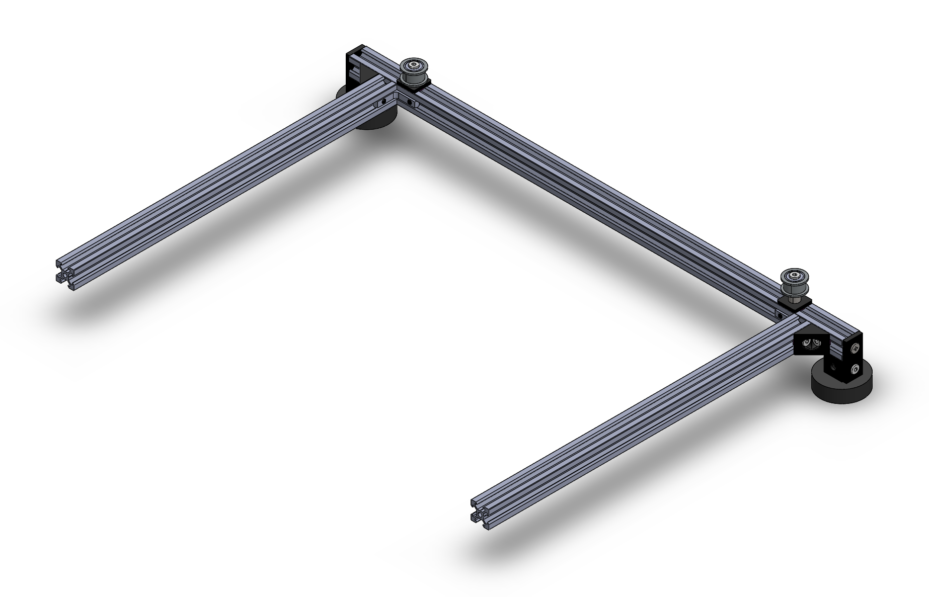
Start by assembling the main frame structure as shown im the image below.
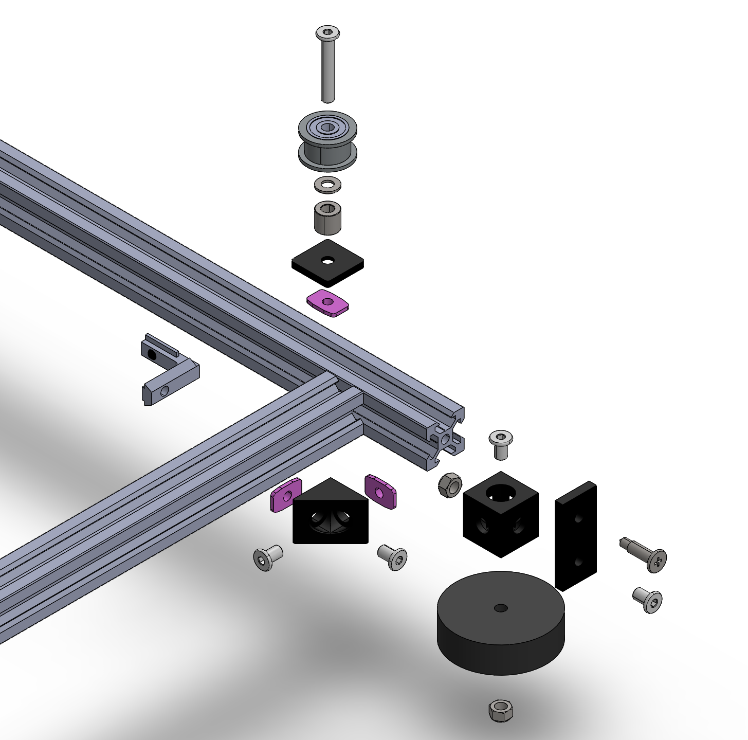
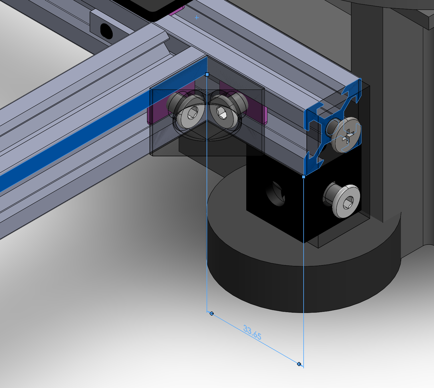
The distance between the x-beam and the y-beam is 33.7.
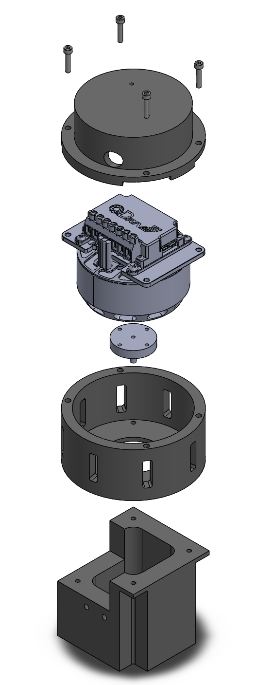
Next we build the motor mounts.
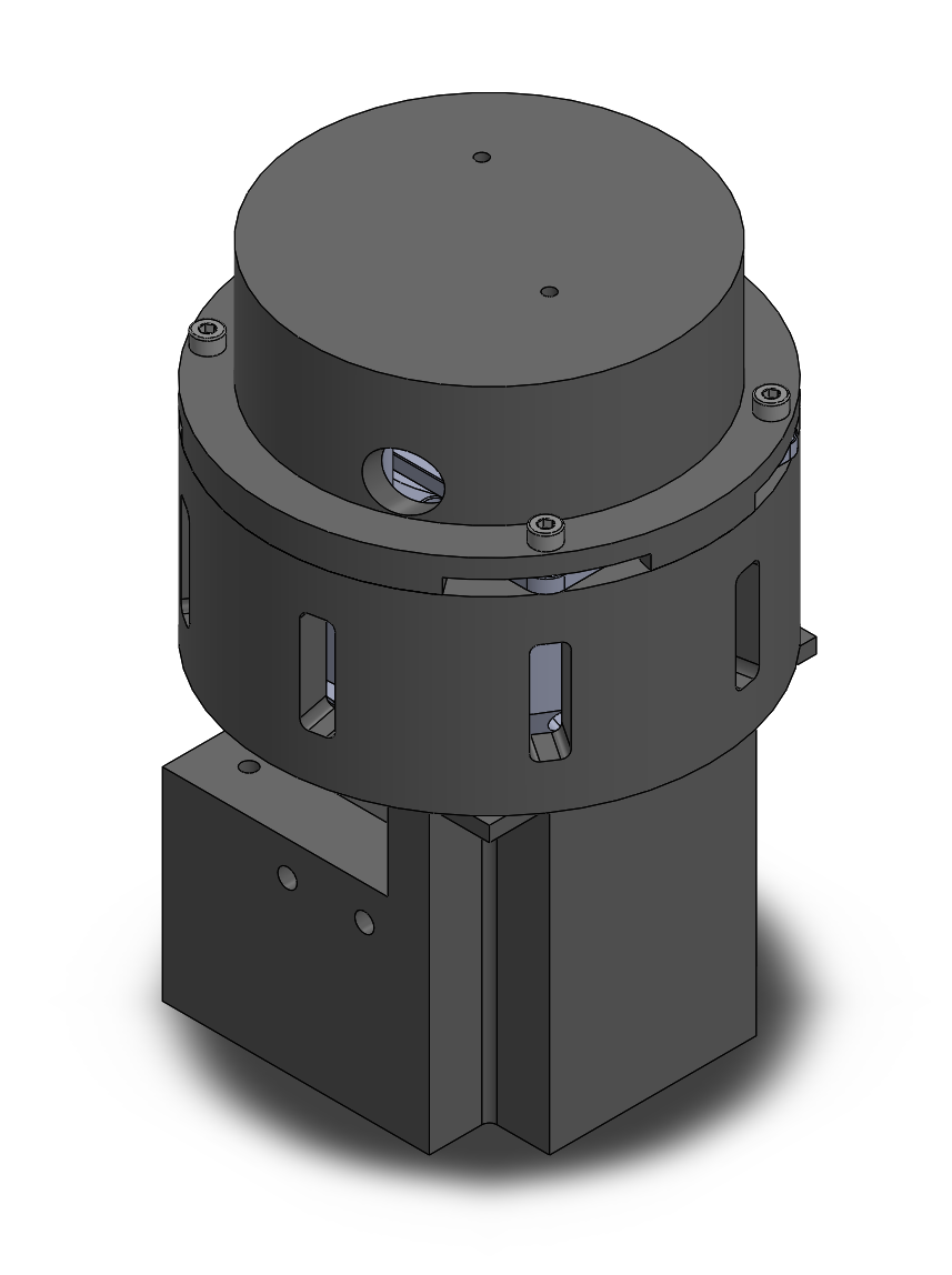
The explosion view below shows how to assemble the motor mounts.
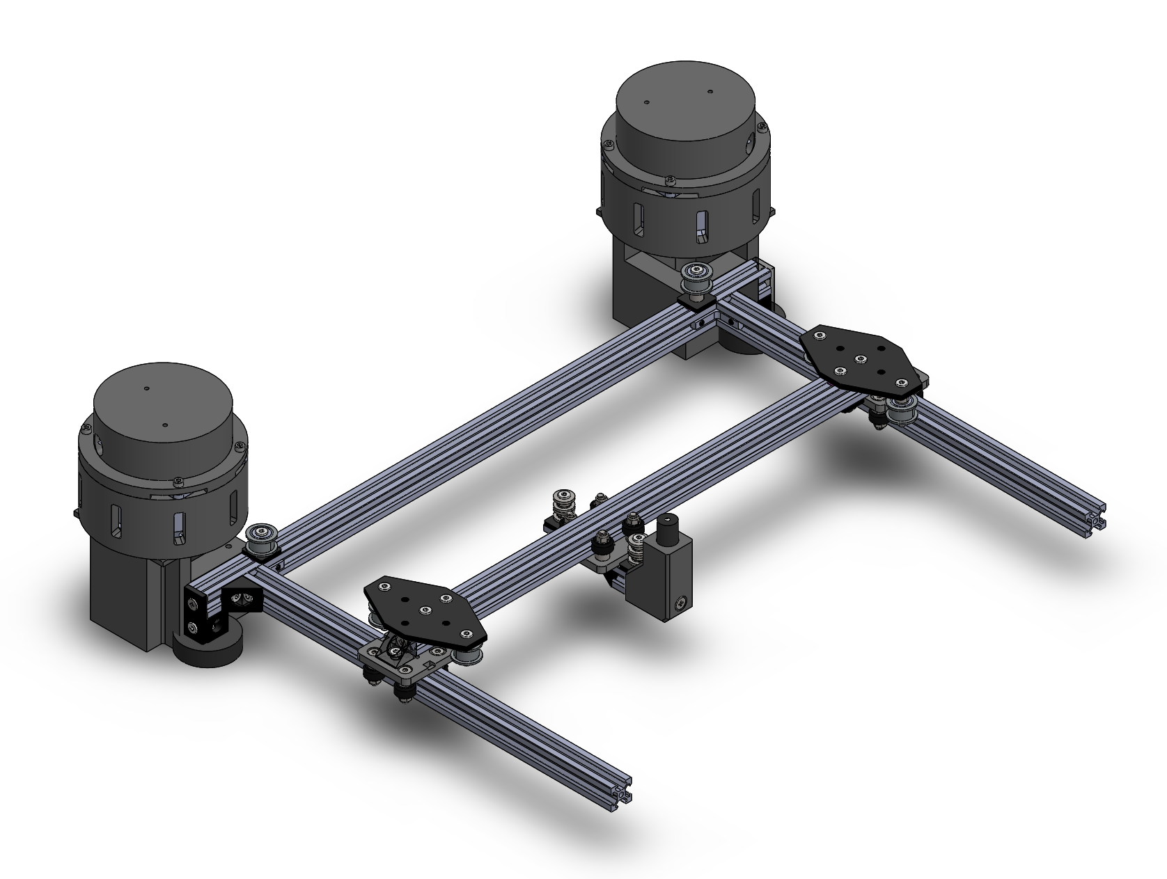
Now you can fix the motor mounts to the previously assembled main frame structure. After that you can slide the bridge onto the gantry frame.
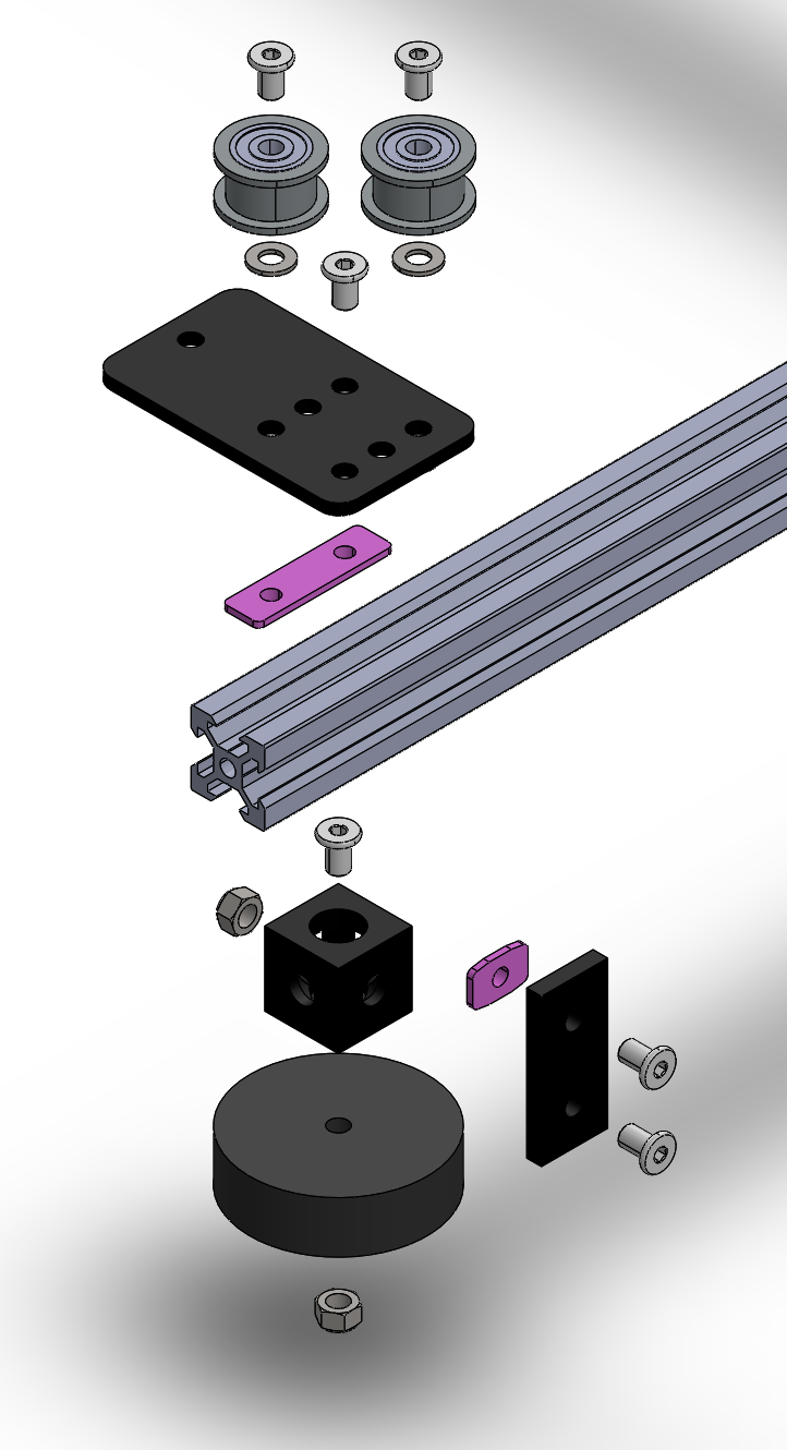
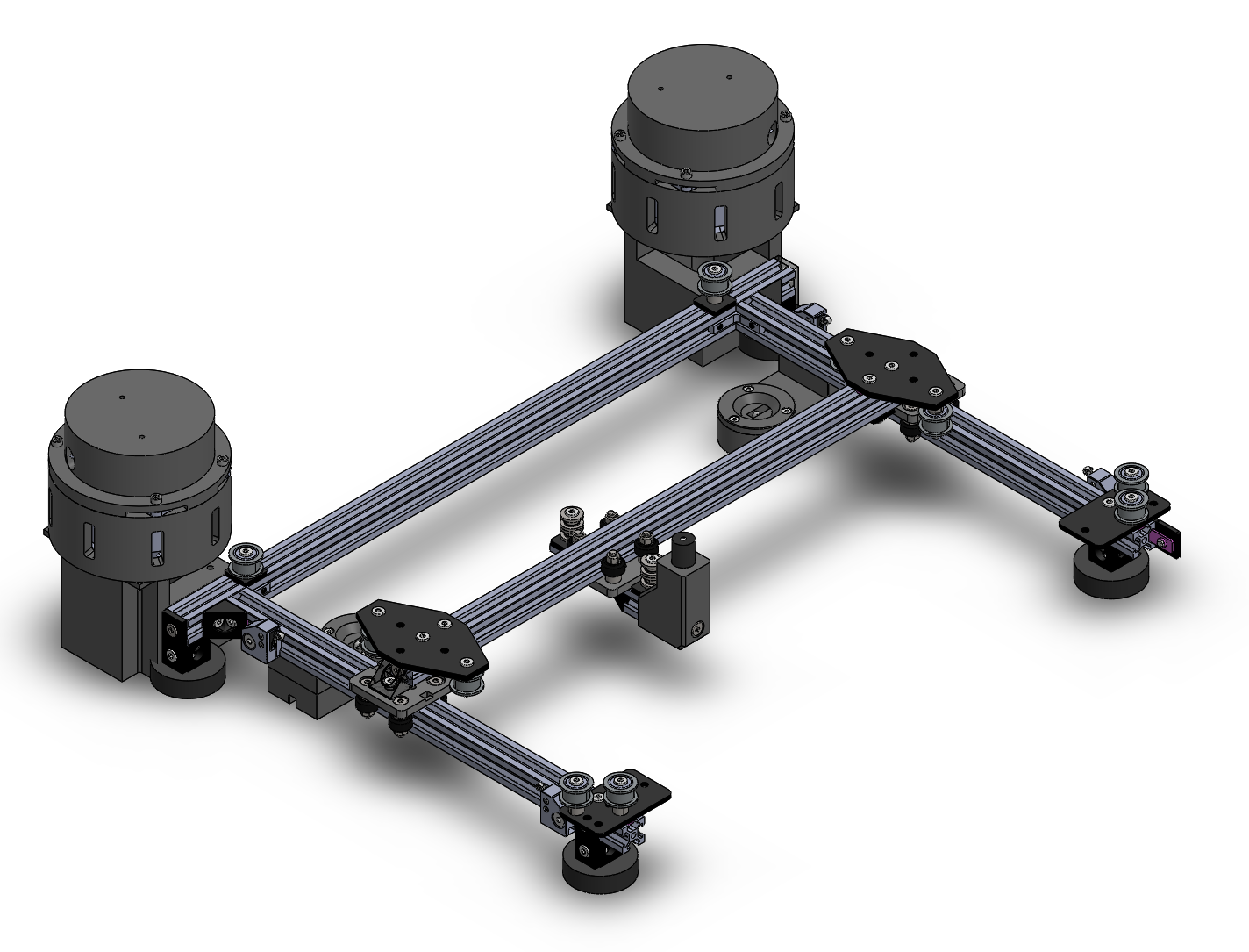
Now you can finish the frame structure by adding the idler wheels and the feet.
With the gantry frame structure finishes we can now add the board frame support and the limit switch mounts.
Belt Tensioning
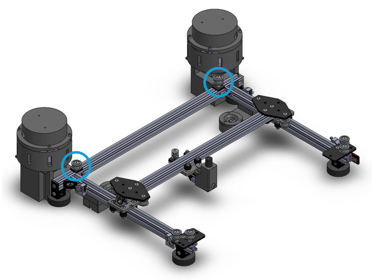
To mount and tension the belts properly we recommend to first loosen the idler pulleys indicated in the image below.
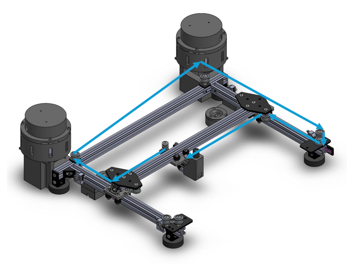
Now fix one end of the first belt to the controller and rout it around the pulleys as shown in the image below.
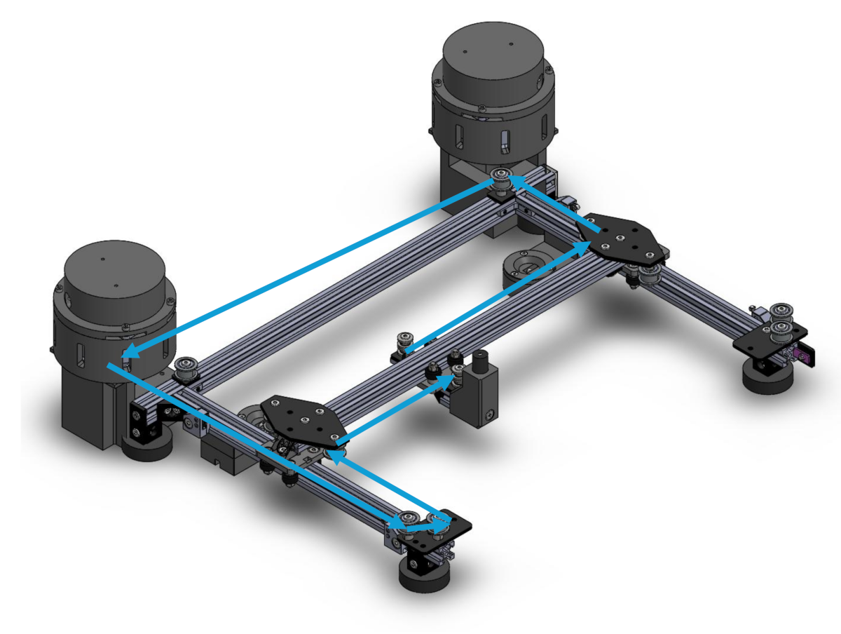
Repeat the same for the second belt.
Finally tension the belt by pulling the loose idler pulley away from the center and re-tighten it.
Overall BOM
A summary of all parts needed to build the complete KLASK hardware system is provided below. Quantities are for 1 camera mount + 1 board frame + 1 gantry system (with quantities for 2 gantry systems shown in brackets).
| Pos. | Name | Description | Quantity | Link |
|---|---|---|---|---|
| V-Slot 20x20 Linear Rail | L = 660 | 1 | Link | |
| V-Slot 20x20 Linear Rail | L = 600 | 2 | Link | |
| V-Slot 20x20 Linear Rail | L = 550 | 1 (2) | Link | |
| V-Slot 20x20 Linear Rail | L = 500 | 6 (8) | Link | |
| V-Slot 20x20 Linear Rail | L = 462.7 | 1 (2) | Link | |
| V-Slot 20x20 Linear Rail | L = 360 | 4 (6) | Link | |
| V-Slot 20x20 Linear Rail | L = 340 | 2 | Link | |
| V-Slot 20x20 Linear Rail | L = 31.5 | 1 (2) | Link | |
| V-Slot 20x20 Linear Rail | L = 26.5 | 1 (2) | Link | |
| Mini V Gantry Kit | 3 (6) | Link | ||
| Black Angle Corner Connector | 18 (26) | Link | ||
| End Cap | 18 (26) | Link | ||
| Inside Hidden Corner Bracket | 2 (4) | Link | ||
| Cross Joining Plate | 2 (4) | Link | ||
| Low Profile Screw | M5x8 | 58 (88) | Link | |
| Low Profile Screw | M5x25 | 2 (4) | Link | |
| Low Profile Screw | M5x30 | 4 (8) | Link | |
| Tee Nut | M5 | 50 (72) | Link | |
| Double Tee Nut | M5 | 7 (14) | Link | |
| Self Tapping Screw | 7 (14) | Link | ||
| Slot Washer - 15x5x2mm | 8 (16) | Link | ||
| Precision Shim - 10x5x1mm | 14 (28) | Link | ||
| Aluminum Spacers | 3mm | 6 (12) | Link | |
| Aluminum Spacers | 9mm | 3 (6) | Link | |
| Smooth Idler Pulley Kit | 10 (20) | Link | ||
| GT2-2M Timing Pulley - 20 Tooth | 2 (4) | Link | ||
| Idler Pulley Plate | 2 (4) | Link | ||
| GT2-2M Timing Belt | 4 m = 13 ft | 1 (2) | Link | |
| Nylon Insert Hex Locknut | M5 | 2 (4) | Link | |
| Rubber Foot | 8 (12) | Link | ||
| Limit Switch | Würth WS-MITV THT (463093370402) | 6 (12) | Link | |
| Socket Head Screw | M2x12 | 8 (16) | ||
| Socket Head Screw | M4x20 | 8 (16) | ||
| Socket Head Screw | M5x30 | 8 (16) | ||
| Countersunk Screw | M2x12 | 4 (8) | ||
| Countersunk Screw | M3x14 | 12 (24) | ||
| Countersunk Screw | M5x18 | 2 (4) | ||
| Hex Nut | M2 | 12 (24) | ||
| Hex Nut | M3 | 12 (24) | ||
| ODrive S1 and M8325s Motor Kit | 2 (4) | Link | ||
| Camera | 1 | |||
| Nanlite Compac 24B | 2 | |||
| Frame Centering Bridge | 3D-Print | 4 | ||
| Camera Mounting Plate | 3D-Print | 1 | ||
| Peg Holder | 3D-Print | 1 (2) | ||
| Ground Plate | 3D-Print | 4 (8) | ||
| Center Plate | 3D-Print | 4 (8) | ||
| Mounting Bracket | 3D-Print | 4 (8) | ||
| Mount | 3D-Print | 1 (2) | ||
| Mount mirrored | 3D-Print | 1 (2) | ||
| Cover | 3D-Print | 1 (2) | ||
| Cover mirrored | 3D-Print | 1 (2) | ||
| Motor Connector | 3D-Print | 2 (4) | ||
| Motor Enclosure Bottom | 3D-Print | 2 (4) | ||
| Motor Enclosure Top | 3D-Print | 2 (4) |